Showing posts with label electronics. Show all posts

Tuesday, 17 January 2017

How to Replace Parts on Circuit Board

Many problems that circuit boards have may be repaired by replacing defective parts. You do not have to be an electronics engineer to remove and replace bad parts. Parts that commonly need to be replaced include capacitors, transistors and various electronic chips. If, through visual inspection or through circuit analysis, you can identify which part is defective, you can usually repair a circuit board.

Identify which part you want to replace on your circuit board. On the other side of the circuit board, there are solder points that connect the parts to the circuit. Identify the soldering points of the part you intend to replace

Heat your soldering iron to operational temperature. Place the circuit board, with the solder side up, on a flat and well-lit surface.

Press the tip of your soldering iron against the solder point that is supporting the part you want to remove. Be careful not to touch the soldering iron to any other parts. The existing solder should soften and turn to liquid. If the solder does not melt, your soldering iron has not reached operational temperature or is not rated at a high enough wattage to melt that specific type of solder. Continue to hold the soldering iron tip in the melted solder.

Suck up the liquid solder using a de-soldering device. There are several types of de-soldering devices, but they all generally work with suction. Repeat this step until all of the solder has been removed from all terminals of the device you intend to replace. De-soldering braid may also be used by placing the braid into the melted solder and allowing it to bond to the braid before pulling it away.

Replace the part that has been disconnected from the circuit board. The old part should come out of the board easily. If it does not, make sure that all of the solder has been removed. Solder the new part into position, ensuring that each terminal is making contact with the correct port in the circuit.
Ways to Tell If a Radio Tube Is Bad

Long before radios went solid-state, they were powered by radio tubes. Somewhat resembling an incandescent light bulb, radio tubes are small, vacuum-sealed devices that burn out from time to time. After the tube goes bad, of course, you'll have to replace it if you want to use the radio again. While tube-equipped radios have not been the most popular kind of radio for decades, many collectors appreciate the beauty and classic engineering of the units. When there is doubt about the health of a radio tube, here's how to tell whether you need a replacement.

Listen for problems in the audio coming out of your radio's speakers. According to Rick's Tube Radios, a defective oscillator tube can cause unwelcome noises in your music.

Verify that the radio's tube heaters are working. According to the Radio Ether Blog, malfunctioning wiring could be a big problem. It may seem impossible to the younger generation, but tube-based radios require a brief warm-up period before the tubes have heated to the point where they are able to function properly. Your radio tube could be in working order, but in need of a little warmth.

Double-check the tube's vacuum seal. Remove the tube from its plug in your radio's innards and examine the outside of the bulb for any sign the seal has been compromised.

Perform a visual check of the complicated wires and circuits inside the radio tube. If there are any loose pieces of metal, the tube's connection could be broken. A tube with discoloration on the glass could mean that a part of the tube has burned out, meaning the whole thing must be replaced.

Install a new tube and see if this fixes the problem. If your radio functions perfectly with the simple addition of a new tube, it's likely that the radio tube was the culprit. If the problem continues, it could be another part of your radio.

What is DIY Night Vision Rifle Scope

Shooting a rifle accurately at a target requires being able to see it. You can make a do-it-yourself (DIY) night vision rifle scope that will let you see what you are shooting at when the lights are out. You will need a few supplies from a hobby store and some experience in using a soldering iron. Get adult supervision if you are underage, since a utility knife must be used to make your DIY night vision rifle scope.

Step 1
Place a sheet of newspaper on a table to protect the surface. Place the Congo blue filter sheet on the newspaper.

Step 2
Stand an empty toilet paper tube on the Congo blue filter sheet. Draw an outline in pencil around the bottom of the empty toilet paper tube, on the Congo blue filter sheet. Remove the empty toilet paper tube from the Congo blue filter sheet.

Step 3
Cut out the outline with a utility knife. Repeat this entire procedure with the empty toilet paper tube and the Primary red filter sheet.

Step 4
Stand the empty toilet paper tube on the newspaper. Heat up a glue gun. Apply hot glue around the rim of the Primary red circle cutout. Place the Primary red circle cutout on the top end of the empty toilet paper tube. Let the hot glue set for five minutes.

Step 5
Apply hot glue around the rim of the Primary red circle cutout. Place the Congo blue circle cutout onto the Primary red circle cutout. Let the hot glue set for five minutes.

Step 6
Cut the empty toilet paper tube in half with the blade of the utility knife. Discard the half of the empty toilet paper tube that does not have the filters glued onto it.

Step 7
Heat up the soldering iron. Place an infrared LED on the newspaper, with the two pins attached to its bottom facing right. Place a button battery on the newspaper next to the two pins, with the Plus (+) contact facing up.

Step 8
Solder the end of the shorter of the two pins to the top of the button battery. Let the solder cool for one minute. Unplug the soldering iron.

Step 9
Place the empty toilet paper tube horizontally on the newspaper, with the end that has the filters on it facing to the right. Apply hot glue to a side of the infrared LED. Place the side of the infrared LED that has the hot glue on it against the top left end of the empty toilet paper tube, with the two pins attached to the LED’s bottom facing to the right. Let the hot glue set for five minutes.

Step 10
Apply hot glue to the bottom right corner of the button battery attached to the infrared LED. Push down on the button battery to secure it to the top of the empty toilet paper tube.

Step 11
Place the DIY night vision scope you have just made on the top of your rifle with the end that has the filters facing you. Secure the DIY night vision scope to the top of the rifle with strips of duct tape. To power the infrared LED, push the longer pin attached to the infrared LED beneath the button battery . Look through your DIY night vision scope to see in the dark.

How to Make Good Toy Train Track

Many toy train collectors and model railroad enthusiasts lack the space needed in a basement or garage to build a permanent layout for running their trains. Even a compact, portable model train table may require more room than is available in the average-sized house or condominium, forcing many would-be modelers to relegate their prized collections to static display cases. For a creative solution to get the trains off the shelves and running on the track, just look up to the ceiling.

Measure the dimensions of the room to create a floor plan drawing, making note of windows and doorways. A basic oval track plan circling the perimeter of the room may be the most practical design. After measuring, verify the train track will fit above the window and door frames yet below the ceiling. Consider a dual-track plan that enables two trains to run simultaneously on parallel tracks, either traveling in opposite directions or racing each other around the room.

Cut the plywood into straight-aways and corner pieces, and lightly sand the edges to remove any splinters. Measure and cut the straight sections, cutting the pieces at least two inches wider than the width of the train track. The corner sections, where the track work curves around the corners of the room, can either fit up against the walls into the corner or can be cut to follow the radius of track to leave an opening between track work and the corner of the room.

Measure and mark the location on the wall for the first plywood section. Use a carpenter’s level to transfer the mark around the perimeter of the room, following the track plan. Mark the locations of the wall studs using a stud finder. Attach the corner molding to the wall along the perimeter mark, securing the molding to the wall studs. The corner molding acts as a ledger board to support the inside of the plywood and track work.

Lay out the straight and corner sections of plywood on the floor, directly under where each piece will hang from the ceiling. Drill holes along the outside edge of the plywood, 5/16 inches in diameter, 6 inches from each end and approximately 24 inches apart along the length of each piece. These holes will accept the threaded rods to support the outside edge of the plywood pieces.

Test fit the train track, centering the track across the width of the plywood and taking care to position a full piece of track across the seams between two plywood sections. If desired, stain or paint the plywood. For convenience, attach as many sections of track as possible to the plywood before mounting the plywood to the ceiling. The National Model Railroad Association recommends attaching the track carefully and securely to the plywood surface for smooth running trains.

Cut the threaded rod to length using the hacksaw. The length of the rod is determined by the distance between the ceiling and the top corner molding, plus two inches. Thread a washer and nut on one end of each rod.

Hold the first section of plywood in position, resting the inside of the piece on the corner molding. If desired, attach the plywood section to the molding with a short screw. Slide a piece of threaded rod up through the bottom of the plywood through one of the pre-drilled holes and up to the ceiling. Use the level to verify the rod is plumb, and mark the location where the rod hits the ceiling.

Drill a hole in the ceiling large enough to insert the hollow wall toggle anchor. With the washer and nut positioned under the plywood, slide the rod up through one of the pre-drilled holes in the plywood, and thread toggle anchor to the end of the rod. The anchors have two small tabs that fold to fit into the hole and then spring open to hold against the inside of the ceiling.

Push the rod and anchor through the hole in the ceiling. The anchor tabs will spring open, holding the rod loosely in place. Repeat with the other rods needed to hold the section in place, and then tighten each of rods into the anchors until the plywood is level.

Repeat with the next section, working around the room until the track plan is elevated and in place below the ceiling. Connect the sections of plywood together with screws. Use the level to ensure the track is flat and level, adjusting the threaded rods as needed to raise or lower the plywood surface.

Making Scenery for Model Trains

Building realistic scenery improves the appearance of a toy train layout and creates a sense of time and place for the model railroad. For many enthusiasts, building scenery is the most satisfying aspect of the hobby. Some model train enthusiasts create landscapes and vistas from their imaginations while others strive to model actual geographic locations and towns in miniature form. Recent advances in modeling techniques, modern materials and the availability of scenic details from several different manufacturers reduces the time, effort and skills needed to build a scenic model railroad.

Draw a track plan that includes the scenic theme and geographic location of your model railroad. Include scenic elements such as mountains, tunnels, bridges, trees, roads and buildings to define the basis of the model railroad: a gritty urban scene, a busy seaport, the rugged mountains of west, a logging railway in the Pacific Northwest, the broad prairies of the Midwest or the rolling Appalachian hills. Transfer the drawing into a full-size track plan and lay out the track work on to the plywood substrate.

Test the completed track work by running trains to identify any problem areas. The trains should run smoothly without any derailments or stalling on the tracks. It is much easier to troubleshoot and correct any track problems or wiring issues before adding the scenic elements to the layout.

Temporarily position the major scenic elements right on the layout, such as mountains and buildings, and then sketch in roads, streams and lakes. Substitute cardboard mock-ups if the model buildings are not yet assembled and ready for use. Test fitting the buildings and other elements in place on the layout allows you to visualize the scenery in relation to the railroad and ensures proper clearances for the passing trains.

Build up the mountains and cut through the tunnel passages. Elevation changes represented by hills and tunnels add visual interest to a model railroad, especially on small layout with a level track plan. Rigid foam insulation is a good choice of material for making mountains. It cuts easily with a serrated knife, and it is a lightweight alternative to the traditional modeling method of plaster-covered cardboard and wire mesh.

Stack the cut pieces of rigid foam insulation until the hills and mountains reached the desired height, then glue the pieces together with a water-soluble adhesive. Fill any gaps with joint compound, and then allow the adhesives to dry and cure. Finish shaping the mountains using the serrated knife or a rasp. If desired, use the tools gouge and roughen areas of the mountains to create a rock-like texture.

Seal the landscape with a coat of latex paint. Use light browns and tans to represent earth-colored soils, covering all of the exposed foam hills and bare plywood areas. Sprinkle a mixture of three or more shades of ground foam into the wet paint in the natural areas such as woodlands and fields. The World’s Greatest Hobby website describes ground foam as small pieces foam dyed in different colors and ground into smaller bits to represent weeds, grass and similar ground covers.

Layer more ground foam as needed to cover the natural areas. Add trees to represent forests, available commercially or made from scale-sized twigs covered in ground foam. Add small rocks and smaller pieces of ground foam in different shades and in various heights and shades of color for a realistic and natural appearance. Some modelers prefer covering hillsides with larger pieces of ground foam or prepared lichen to represent a canopy of trees rather than placing individual trees to create a forest scene.

Create urban scenes with buildings, roads, vehicles and pedestrians. Small details add a sense of movement and life to model railroad. Most towns have a passenger station and industries serviced by the railroads, offering scenic opportunities to add details such as streetlights, signs, benches, trashcans, equipment, workers and other bits of urban life.

Track to Use for Outdoor G Scale Trains

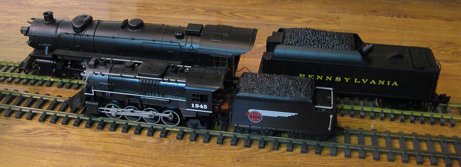
G scale trains were created large so they could be run in large spaces like a garden. Since the rails are woven in and around landscaping, it's easier to leave them outdoors year round. Yes, the trains can be run any time of year, but the tracks are subjected to all kinds of weather conditions. So the tracks are built rugged and sturdy to stand up to worst that the weather has to offer.

Image result for G scale trainsHistory
Bachmann G scale trains are modeled after North American narrow-gauge railroads. The rail spans and rail height on the track were scaled proportional to real life narrow-gauge railroads. Other G gauge trains were modeled after standard scale trains (Burlington Northern or Santa Fe).

Expert Insight
Paul D. Race manages "Family Garden Trains," a website devoted to reviewing G scale garden trains and tracks. Since 1996 he has become the "go to" person for questions about G scale railroading and garden track issues. Race recommends that beginners "consider installing a small test loop outside. This is a temporary one to two-year installation to give you the general feel for what it is like to have a garden railroad." He also suggests setting it up in a location separate from the permanent layout sight so train operation can continue during permanent layout construction.

Size
G gauge track has a rail span of 1.775 inches or 45 mm and is called code 332 because the rail height is .332 inches. The track scale (which is different than track gauge) is 1:20.3 up to 1:32, meaning 1 foot of 1:20.3 G scale track is equivalent to 20.3 feet of real life track. Most G scale trains can handle a 2-foot radius curve, but as a general rule Garden Railways Magazine suggests using a 7- to 8-foot radius because it creates a more realistic look when trains navigate the curves.

Types
Most G scale track is made from brass because it resists weathering. However, rising copper prices mean more expensive brass tracks. One way to lower costs is to use code 250 (1/4-inch rails) track instead of code 332 track. It looks more like the prototype, but isn't as durable. Another cost effective alternative is aluminum tracks. Weathering creates aluminum oxide which conducts electricity (brass oxide doesn't). Aluminum rails come in flex track, produced in curveable track sections which makes it easy to create free-form curves, though they need a heartier roadbed, such as concrete.

Considerations
Laying track outdoors will take a little work. First, excavate two- to three-inch deep channels where tracks will be placed. Next, pack the channels with crushed rock up to the bottom of the rail ties. Make use of rough-edged rocks that will lock against each other when tamped into place with a stick or brick. Next, position and level the track over the ballast bed. Then place a bit more ballast between the rail ties and tamp it into place to hold the rails firmly in place. Ballast may need occasional re-tamping as it will shift due to seasonal changes.

Simple Tips to Build Good RC Drift Track

Building a radio-controlled track for drifting is no small feat. Many different things must be accounted for, such as the track surface, amount of corners, width of the track and barriers. Building a successful drifting track may also be costly, because of the amount of materials and time that must be put into the track. Radio-controlled drifting competitions normally calculate points based on the drifting used and the position the vehicle finishes in. It is important to have the correct surface to balance friction between the track and tires.

How to Build Good RC Drift Track
Set aside about 50 square feet of space to create the drifting track. Prime areas for a drifting track would be in a private lot or large basement. Measure the area using the measuring tape, and mark the area with cones or small flags.

Place the cement mix in a wheelbarrow with the help of a shovel. Combine water and the cement mix to create concrete. Use this to create a 50-square-foot surface area about 2 inches thick. This will be the low-friction surface used for drifting the radio-controlled cars on. Let the concrete harden for 24 hours.

Design a track with multiple turns and straightaways, using graph paper and pencil. Determine the size of the turns for drifting. The turns can either be sharp or wide. Designing the track is a matter of personal preference.

Create the outer lines of the track on the concrete surface, using white spray paint. The lanes should be about 4 feet wide. Measure the lane width for equality, using the measuring tape. The outer lanes should match up with the track design that was drawn to scale. Paint the start and finish line on the track with the white spray paint.

Create the point zones for drifting with the yellow spray paint. Spray an even coat of paint around the center of each turn. During a drift in this zone, points will be allotted to the driver.

Line the perimeter of the track with plastic tubes to prevent damage to the vehicles if they lose control. Screw the barriers in place with 4-inch screws using a power drill. Medium-sized soft, hollow electrical tubes work best--as opposed to a hard, polyvinyl tube--because they will minimize damage to the vehicles if they are hit.

Adorn the track with racing decorations, if desired. Flags, artificial turf and sponsor banners are just a few different things that can be used to decorate the track to make it look more professional.

Tips to Calculate Conical Taper

Conical taper is the change in the diameter of a circular solid along its length. It can be expressed in linear units such as inches per foot or as an angle. When the decrease in diameter and the length are viewed as two sides of a right triangle, trigonometry can be used to convert the linear unit expression to an angle. A trigonometric calculator will do the conversion automatically. Trigonometric calculators are available online for free.

Convert the units of the conical taper so that all units are the same. If the taper unit is inches per foot, divide by 12 to make it inches per inch. Three inches per one foot would equal 0.25 inches per inch.

Visualize a cross section of the cone with the length being the height and the diameter being the base. The point of the cone is at the top of the triangle. The conical angle is the angle formed at the top of the triangle when a line is drawn straight down the center forming two right triangles.

Calculate the tangent of this angle by dividing half of the base distance of the original triangle by the height. For a conical taper of 0.25 inches per inch, divide 0.125 by 1. This equals 0.125 inches.

Use a trigonometric calculator or trigonometric tables to find the angle with the tangent you calculated. The angle with a tangent of 0.125 inches is 7.12 degrees. This is the conical taper expressed as an angle.

Easy Tips to Repair Lionel Train Tracks

Lionel toy trains run on O gauge and O27 gauge three-rail track, and today's hobbyists can chose between traditional O gauge and standard O gauge track when designing and building an electric train layout. Standard O gauge track features a realistic appearance with numerous railroad ties and larger radius curves while traditional O gauge uses tighter radius curves with the familiar toy-like appearance of tubular construction. Both types of train track are desirable and durable, and even neglected track that is dirty, bent or rusting requires just a few minutes and a few simple tools to clean and repair for use on a Lionel toy train layout.

Inspect the track for dirt, rust and damage. The train track carries the electrical current from the power pack to the trains, and must be clean and aligned properly. The center rail carries the electrical current while the two outside rails guide the wheels of the train and provide the ground to complete the circuit. Rollers mounted to the underside of Lionel engines, tenders and specialty cars pick up the electrical current from the center rail.

Clean the train track using a light coat of penetrating oil. Spray a small amount of oil on to a clean cotton cloth, and wipe the rails to remove dirt and grease. Use a second cotton cloth to dry the train track. Lionel recommends using a utility knife or similar tool to scrape off any stubborn dirt or grease. For rusted rails, use a piece of 150-grit or finer sandpaper to lightly scour the track, followed by a cleaning with the penetrating oil and cloth.

Crimp any loose pins. Three metal pins, inserted at one end of each section of track, transfers the electrical connection to the next piece of sectional train track. The pins should fit tightly inside the tubular rails. Loose or rusted pins can inhibit the electrical connection, causing the train to lose power and stall. Use a pair of needle-nose or diagonal pliers to crimp the rail flanges tightly around the pin. Replace any broken or severely rusted pins.

Check the rail ties. Each piece of Lionel traditional O gauge train track uses three metal ties to keep the rails aligned properly and to secure the track to the layout, while standard O gauge track has many ties with clips to keep the rails in place. Inspect each of the clips holding the rails to the ties, replacing any ties that are missing or deformed. The center rail uses a small piece of cardboard or rubber to insulate the rail from metal ties, preventing an electrical short-circuit between the three rails. Replace any worn or missing insulators.

Straighten any bent or kinked train track. Using needle-nose pliers, apply light pressure against any kinked or bent rails, gently easing them back into their original position. Lionel train track is flexible, and proper alignment is necessary to reduce engine and car derailments.

Easy Tips to Build Roller Coaster Model

Building a model roller coaster is a great, hands-on way to learn about physics and centrifugal force. Whether you plan to build a roller coaster for fun or for learning, you will no doubt be able to see how the Laws of Motion apply and how gravity and friction affect your finished coaster. There are hundreds of real coasters that can be used as a design for your model, or you can design a new coaster and see how it stands against the real ones.

Easy Tips to Build Roller Coaster Model
Study photos of your chosen coaster, or use paper and pencil to design your own. You will need

views from many different angles so you can accurately reproduce the coaster. You will also need the measurements so you can convert them into scale and your model will fit together correctly.

Prepare the base of foam core to hold your finished model. Use the measurements to find the widest and longest parts and make sure that you center the coaster on the foam core so nothing is hanging off when the model is complete.

Using your chosen scale, plot out the points that will create your tracks. Points should be in pairs to represent the support beams on each side of the track. Use the pencil to connect these points to make a 2D image of the track.

Stick the skewers into the points you plotted to represent the support beams. Put a drop of glue on the dot and insert the skewer with the pointed end going into the foam core. Allow these to dry completely.

Use toothpicks to make support beams that run between the skewers like rungs on a ladder. Attach them with string or glue or both. The top "rung" of these ladders will be the supports to the tracks.

Add any scenery or decoration to the base that you would like to. Some ideas would be trees, benches, shaved coconut dyed green for grass or paint to simulate concrete or pavement.

Use long strips of balsa wood around the outside of the support skewers to give the coaster more strength and stability. Begin these at even intervals that are equal to the spacing of the support skewers.

Begin to construct the tracks using the balsa wood strips and the toothpick rungs. Start with a flat section such as the beginning or the ending of the track. Use string to keep pressure on the balsa wood until the glue dries.

Snip the tops of the skewers so they only extend 1 inch above the track. Lay strips of balsa wood over these skewers to simulate railings.

Continue constructing the track one element at a time. Use string to keep elements secure while the glue is drying. Especially if you are creating loops and curves.

Add all the fixtures that are near actual roller coasters. Such elements could include the design the line moves in, the covered area for loading passengers and lighting along the tracks and lines.

Paint the coaster, if desired, after all the glue has set.

Test your coaster with a car built for it, or a marble placed on the tracks.

Tips to Increase Range of Remote Control Cars

Many remote controlled cars can drive up to about 100 feet. After that distance, the receiver, which is located in the radio controlled car, starts to lose the signal from the transmitter, which is the hand controller. There are aftermarket transmitters and receivers that help extend the distance of the radio controlled vehicle. Other options include working with the antenna on the vehicle. If the antenna is not high enough on the car, the distance will be dramatically shorter.

Remove the stock receiver from the radio controlled car. Unplug the wires connecting the receiver to the power source and motor. Remove the screws holding the receiver in place using a Phillips screwdriver.

Place an aftermarket receiver in the radio controlled car. This higher-powered receiver will allow the car to travel farther. Screw the receiver in place. If the aftermarket receiver cannot be screwed into the pre-drilled holes in the car's chassis, tape the receiver in place with double-sided foam tape. Connect the power and motor wires to the receiver.

Purchase an aftermarket hand-held transmitter that has equal power to the receiver. The frequency crystals must match for the transmitter and receiver to communicate with one another. The transmitter and crystals can be purchased in any hobby retail store or from online hobby specialists.

Inspect the antenna on the radio controlled car. Run the antenna through the antenna tube. Secure the tube in the pre-drilled hole in the car's chassis, which holds the tube vertically on the car. More distance can be gained from the car due to the higher antenna.

Replace the stock antenna on the transmitter with a longer aftermarket antenna. Aftermarket antennas can be purchased at any hobby retailer. Twist the stock antenna counterclockwise until it is fully unscrewed from the transmitter. Insert the aftermarket antenna in place of the stock antenna. Twist the new antenna clockwise until it is snug in place. Turn on the transmitter first, and then the car. Drive the vehicle to make sure all the components work properly.

Compound Versus Sliding Compound Miter Saws

The compound miter saw is a specialized power tool used for making crosscuts in lumber and other materials. It consists of a motor and blade combination mounted on a pivoting arm that is brought down to the material by pulling on a handle. The cuts made by the saw are precise and repeatable because the pivot point is fixed to the heavy base of the tool. The sliding compound miter saw adds depth to the myriad adjustments that are set for a cut by mounting blade and motor on rails.

Compound Miter Saws
The compound miter saw has a fixed motor-blade combination on its pivoting arm. The "compound" refers to the angle of the blade that can be adjusted on both the vertical and horizontal planes, allowing the user to make cuts with compound angles. Material is clamped to the base of the saw and the precision of the angle adjustment mechanisms makes repeated cuts that are exactly alike.

Sliding Compound Miter Saws
A sliding compound miter saw adds a rail or rails to the tool that allows the motor-blade head to slide front to back during the cut operation. This simple addition to the tool extends the width of the material the tool can cut. The sliding mechanism, however, limits the thickness of material that it can accommodate because the range of the pivot mechanism must be narrowed.

Cutting Height
Compound miter saws have a height advantage in the greater cutting arc not limited by the sliding rails. This arc enables the saw to cut thicker material with the same size blade. This consideration is also important if the saw is going to be used to cut tall moldings for corner joints.

Cutting Width
The rail component of the sliding compound miter saw enables the cutting head to slide along a fixed path, allowing it to cut wider materials. The compound miter saw is limited in the width that it can cut in one stroke by the size of the blade it uses. Consumer miter saws are built to use blades from eight to 15 inches in diameter, with most popular sizes being a 10- or 12-inch blade. A 10-inch compound miter saw can cut material that is two inches thick by six inches wide. A sliding miter saw with a 12-inch blade expands to handle material 4 1/2 inches thick and 12 1/2 inches wide.

Choosing a Compound Miter Saw
Either the sliding or fixed compound miter saw will make angled and square cuts as required by the craftsman. If the saw is to be used exclusively for smaller materials, the compound miter saw is a good choice for making precision cuts. The significant additional cost of the sliding compound miter saw is justified if the craftsman is going to routinely need to cut wider and taller materials that can only be accommodated by this type of tool.

Building Ham Radio 900 MHz Antenna

The amateur 902-928 MHz band holds several advantages over other bands for novices. Because little or no commercially-produced equipment is available specifically for amateur use, traffic on the band is limited. This creates 26 MHz of mostly interference-free bandwidth for experimenters to play with. Equipment is no problem, either. Cell phones that work on the defunct analog network can be had very cheaply or for free and the same is true of cordless phones and other 900 MHz Part-15 devices. All of these devices contain the basic transmitters and receivers needed for 900 MHz operation. The only thing lacking is an inexpensive high-gain omnidirectional antenna, but that is not too difficult to make at home.

Cut the coax cable to eight inches. This will become the antenna itself after separating the two conductors so that they become elements of an end-fed dipole.

Measure back four inches from the cut end of the coax and, with a sharp knife, score the outer insulating layer all the way around. Be careful not to nick the wire braid which lies just underneath the insulation.

Remove the section of insulation that you just freed; it should slip off with little resistance.

Push the braid from the end, so it expands slightly while pulling back from the center conductor. Pull the braid from just above the cut end of the jacket so that the braid begins turning inside out and folding back over the remaining insulation. Continue pushing the braid until it folds completely back over the insulation, forming a tube that extends almost to the connector. When finished, the outer braid should be folded back sharply from the center conductor at the point that the insulation ends. This fold becomes the feed point, with the center conductor becoming one half of the dipole and the tube, formed of the outer braid, becoming the other half.

Tin about two inches of the braid with the soldering iron and solder. Start about a half inch below the fold.

Measure 3.2 inches back from the fold, using the caliper for precision, and carefully trim the excess braid from this point. Use sharp wire cutters for this.

Measure the exposed center conductor 3.2 inches from the fold, again using the caliper. Cut the excess with the wire cutters.

Cut a piece of heat-shrink tubing long enough to cover the entire antenna. Slip it over the antenna. Turn the heat gun on the low setting, and move the gun back and forth along the length of the tubing until it shrinks. Be careful to hold the heat gun three to four inches away and keep it moving, so as not to overheat and damage the antenna.

Slip the soda straw over the antenna to stiffen it. Then slip a second piece of heat-shrink tubing over the straw, and shrink it with the heat gun, again moving the heat along the length of the tubing.

Fun Things to Do With Lawnmower Engine

Archimedes once famously said: "Give me a lever long enough, and a prop strong enough, I can single-handed move the world." Small engines are like Archimedes' lever, all kinds of potential just waiting to be unleashed. Four-stroke lawnmower engines are perfect foundations for a number of projects, especially those that require the low-end torque and durability of such designs.

Go-Kart
Lawnmower engines are essentially just downsized car engines. At least, that's the thinking of the many who have converted these former mulchers into tire-shredding go-karts. Some of the fastest go-karts around are powered by modified 15 to 20 horsepower engines that either came from lawnmowers or could have if they hadn't been snatched up by the go-fast crowd first. Lest you think that such go-karts are slow, consider this: a 20 horsepower engine in a go-kart weighting 80 lbs. with a 200 lb. driver would yield about the same power-to-weight ratio as a 200 horsepower 2010 Honda Civic (about 14 lbs. per horsepower).

Generator
Arguably less fun than go-karts but far more practical, generator conversions are a natural fit for lawnmower engines. Mower engines are deigned to run for hours on end using as little fuel as possible, all without overheating. Mower-powered generators are pretty easy to build with a few scrap alternators. Generally speaking, an alternator will take about 5 horsepower to turn at full output, which equates to about 3,000 watts with an 80 percent efficient alternator. For a 20 horsepower engine using four alternators, that comes out to 12,000 watts (about 110 amps at a standard 110 volt house current). That's enough to run most homes' basic support systems (like the fridge, water pump, some lights, a TV and a microwave) for short periods.

Log Splitter
Building a log splitter may require extra parts and some additional cash outlay, but these handy devices can save hours of back-breaking labor in the wintertime and may justify the cost in the long run. A log splitter is basically composed of a power unit (the engine), a hydraulic pump, a hydraulic ram and a few bits of plumbing. Essentially, the motor drives the pump, which sends pressure to the hydraulic ram. The ram pushes the wedge into the log, splitting it in two. If you're scavenging the motor from a zero-turn mower, you'll already have the hydraulic pump (which is a big chunk of the extra cost). Otherwise, as of 2010 a brand-new hydraulic pump and ram will cost you from $100 to $300 (pump) and $300 to $400 (ram). The end result is a log-splitter that could cost at least $1,500 new. Better yet, you can recoup some of that cost by splitting logs for your friends.

Tips to Use Virtual DJ Pro

Virtual DJ is software for computer-based audio and video mixing. There are a number of versions and they vary in price. The flagship version is Virtual DJ Pro. Two principal differences between Virtual DJ Basic and the next level, Virtual DJ Pro, are that the Pro version will output video in full screen and there is timecode vinyl control support. Experiment with these useful upgrades.

Experiment with timecode vinyl control. Connect the timecode control component (turntable) to the soundcard. The left control connects to Input 1 and the right control to Input 2. Set the soundcard to "Phono" for each input. Set up the soundcard in Virtual DJ. Click on the Config button in the upper right corner of the skin and select your soundcard. On the soundcard tab, select the input's dropdown and select the Timecodes option.

Set the appropriate Digital Vinyl System (DVS) signal for your DVS. Choose the DVS that you are using. For example, manufacturer Serato Vinyl. Virtual DJ will support most (DVS) signals.

Start playing the DVS Vinyl and look at the display. You should see the 100% Quality signal. If you don't, adjust the global settings like Left/Right, Phase/Anti, Gain and Silence in that dialog box until you get to 100% quality. Click "OK" to close the Timecode dialog box. Click "Apply" to commit the settings and then "OK" to close the dialog box.

Output some video in full screen mode. Look in the browser for video files. They are distinguished with a blue "V" symbol within the file icon. Video files linked to audio files will be marked with a blue "L" symbol in the icon. Play a video or a video-linked audio file by dragging it to a control area---a turntable deck, for example. The video window will open, which in Virtual DJ Pro will be full screen, as opposed to other versions, which will output as windowed output.

How to Make Model Amusement Park

If you are a seasoned model builder or toy train enthusiast, then building a miniature amusement park is the challenge you have been looking for. Kevin Jones, a professional model amusement ride builder, recalls on his website, ScaleCarnivalRides.com, that his family's business grew out of a love of setting up a toy train Christmas scene each year. Building an amusement park will take more time and energy than the seasonal display, but will be labor of love for the entire family to enjoy.

Pick a space to build your ride kingdom. A theme park is going to take considerable space; at the very least, you will need a 4-foot by 8-foot sheet of plywood to work on. However, if you have the space, a theme park model can easily fill a garage or section of your basement.

Choose the model's scale. Many kits and pre-made pieces follow the popular model railroad sizes (N, HO, O and G). For your model to look realistic, you will need to adhere to the same scale for all the pieces. N-scale is 1/160 of actual size, which will allow you to fit more pieces in a tight space, however working with small parts can be tedious and frustrating. HO-scale at 1/87 actual size and O-scale, at 1/48 of actual size are most popular scales given that the majority of model train enthusiast use these two sizes. Professional roller coaster model builder John Hunt makes most of his models to match the HO scale.

Draft your layout. Whether on graph paper or using a CAD program, you will need to map out your park. Like a real amusement park, there are too many elements in play to place pieces haphazardly. Consider incorporating a model train set riding around the perimeter of the park.

Decide if you will build your rides from scratch by using a kit or purchase pre-made rides. The Internet is full of enthusiasts who will build custom models of your favorite real park attractions to the scale of your choice. Similarly, there are companies that build kits of standard rides, such as Ferris wheels and carousels. Just remember to choose the correct scale.

Build your park one section at a time. Enhance your fun by building the park in planned phases, like a real amusement park. Complete the front section with a couple rides first. Then, you can place "caution" and "under construction" signs to block off the incomplete areas until they are finished. This way, your park can entertain "guests" and begin a revenue stream while still under construction.

Tips to Install a Blower Motor

A blower motor is a small motor with a fan used for cooling and ventilating. There is a blower motor in almost every type of car, simply because there is always a need to cool down a heater or to manage an air-conditioning system. The speed of the blower motor is regulated with a resistor, which basically makes the blower motor spin faster. Installing a blower motor is a fairly easy task that can be done by almost any car owner and it differs only slightly from one model of car to another.

Open the hood of your car and support it with a rod while you work. Locate the battery inside the hood and use a socket wrench to remove the negative battery cable. Use black electrical tape to wrap the end of the cable completely and securely. Do not let the metal end of the cable touch the engine or any other metal under the hood.

Locate the blower motor in your vehicle. The exact location of the blower motor differs depending on the model of the car but it is usually under the dashboard, on the passenger's side of the car.

Open the passenger's door and remove the screws from the trim panel located just under the glove compartment. Use a Phillips-head screwdriver to remove the screws and then a pry tool to detach the insulator panel from the dashboard.

Disconnect the wiring harness by using a flat-head screwdriver to unplug the retaining clamp. This will release the electrical connector and you will be able to disconnect the wires safely.

Remove the retaining bolts that hold the blower motor in its place. Use a ratchet and socket set to loosen and then completely remove the bolts. Then carefully and gently pull out the old blower motor and put it aside.

Insert the new blower motor in the place of the old one. If you chose the right model, your new blower motor should fit perfectly into place. Using a waterproof silicone sealant on the rim of the blower motor's base is recommended. Apply a small amount on the mounting base before screwing it in position.

Mount the new blower motor to the housing by securing it with retaining screws.

Connect the wiring harness of the blower motor and the car. If you chose a compatible blower motor, simply connect the harness plug by clicking it into place.

Reinstall the insulation and trim panel back under the glove compartment by securing it with screws.

Reattach the negative cable of your car battery and close the hood.

Test your new blower motor by turning on the ignition and starting the heater. If you hear a steady, smooth sound coming from the blower motor, that means the installation was a success.

Tips to Calculate Amps to KVA

A KVA (kilovolt ampere) is a unit that measures power. The unit itself is similar to a watt, the number of volts times the number of amperes, divided by 1,000. A KVA is used generally with AC current with the addition of a power factor, a factor that accounts for variations in current and voltage.

Step 1
Multiply the number of KVA by 1,000 to convert from KVA to regular volt amperes (VA). If you have 1 KVA, this equals 1,000 VA.

Step 2
Multiply the number of VA by the power factor, which will be particular to your equipment or setup. If you don't know the power factor, use .6, which is an industry standard. Given 1,000 VA times a .6 power factor, you get a figure of 600.

Step 3
Divide your figure from Step 2 by the voltage in your system to get your final calculation of amps. Typical voltage in the United States is 120, so in this example, your amperage is 600 divided by 120, or 5 amps.

Making Model Train Bridge in HO Scale

Model train bridges add greatly to the look of a model railroad setup. The bridge gives height to your model, creating an additional layer to your railroad build that aids in immersion and realism. Because of the small size of an HO scale layout, you can build bridges that seemingly stretch across wide chasms, over deep gorges, or crossing over busy city streets in an urban setting. The variety possible with HO scale brides is largely unlimited, but regardless of the design, the basic parts and procedures for building an HO scale model train bridge remain the same.

Measure the distance that you're covering with the bridge and purchase an HO scaled bridge of the appropriate length. Measure the distance from where the bridge will lie to the bottom of the bridged area. Purchase HO scale piers that are long enough to reach to the bottom of the bridged area when evenly spaced along the length of the bridge. Each bridge manufacturer has a recommended number of bridge piers.

Cut the board edges along the bridge route bordering the area you're bridging over. Cut the sides so that the bridge abutment fits snugly against it. The abutment is the concrete or stone model wall piece that sits at the edge of the chasm and supports the ends of the bridge. Sand the edges level with the sandpaper so that you can place the abutment securely against the opening to the covered area.

Glue the abutments in place against the sides of the area to be covered using epoxy glue. Make sure that you place the abutments parallel to one another and that the tops form a level plane to one another. You can check that they are level using a carpenter's level placed across the abutment pieces.

Place the bridge piers evenly spaced along the bottom of the bridged area in line with the abutments. Test the placement of the piers by laying the bridge over them, adjustment pier placement as needed. Glue the bridge pieces in place using epoxy glue. Allow the glue to set for 15 minutes.

Glue the bridge into place, covering the abutments and piers. Place a dab of glue along each pier and along the abutment and then hold the bridge in place for 30 seconds to begin the glue setting. Allow a further 15 minutes for the glue to set.

Run the flex track over the placed bridge. Glue the cork roadbed for your track onto the surface of the bridge with epoxy glue, waiting 15 minutes for the glue to set. Place the track over the roadbed, and then connect the bridge track to the track on either side of the bridge to complete the installation. Glue the track to the roadbed by diluting white glue to a 25 percent solution. Brush the railroad ties of the track to the roadbed and allow the glue to set overnight.

The AC & DC Coupling Oscilloscopes

Most oscilloscopes have two types of input coupling to handle both alternating current and direct current signals; typically, a switch lets you select AC or DC to suit your measurement needs. When you set an input to DC coupling, the oscilloscope displays both AC and DC signals, although AC signals may pose a problem. By switching to AC coupling, the scope displays only AC signals; this simplifies measuring certain electronic circuits.

DC Coupling
The DC coupling setting provides a direct electrical path into the scope; it accepts all types of signals, including unchanging DC voltages, time-varying DC voltages, AC, and combinations of AC and DC. In the last case, technicians call it an AC signal with a DC offset. Sometimes, DC offsets can be bothersome; the total signal voltage may push the signal past the top or bottom of the display, hiding the parts you want to see. However, under most other circumstances, DC coupling is all you need.

AC Coupling
With AC coupling, the oscilloscope’s input has a capacitor in the signal path, removing DC offset from any mixed signal and letting you see the AC part more easily. For example, some transistor and vacuum-tube amplifiers have a significant DC offset; removing it with AC coupling helps you troubleshoot these circuits. Although it is most helpful with mixed signals, AC coupling also works with pure AC signals. Because it blocks DC, it is not suitable for DC signals.

Twitter Delicious Facebook Digg Stumbleupon Favorites More

 
Design by Free WordPress Themes | Bloggerized by Lasantha - Premium Blogger Themes | Affiliate Network Reviews